Chinese Coordinate Systems and Bing Maps in Civil 3D
Overlayed map data from different sources (like from multiple digital maps, redline coordinates, survey and GPS data) often missmatch. Most likely the drawings using different geographic coordinate systems and projections. Manually moving them to matching points may lead to serious errors when you have to give coordinates back for permits or construction and your drawings may missmatch your clients drawing. Setting the drawings in to the right system could solve this.
This tutorial covers the basics of finding the matching coordinate system and adjusting the background map in Civil 3D. Adjustments needed to adjust some obfuscation in Chinese digital maps regarding to national security concerns https://en.wikipedia.org/wiki/Restrictions_on_geographic_data_in_China will be covered in a separeted tutorial.
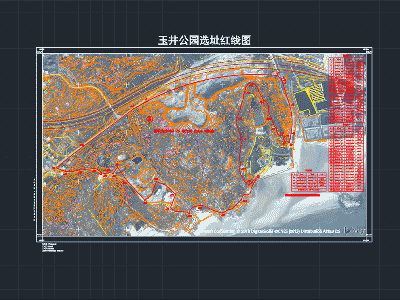
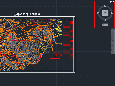
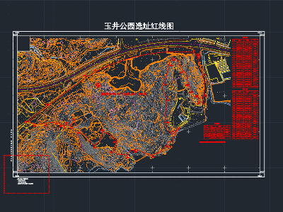
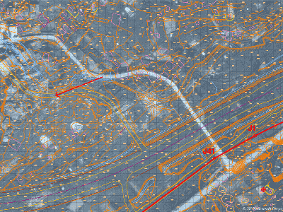
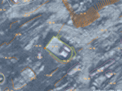
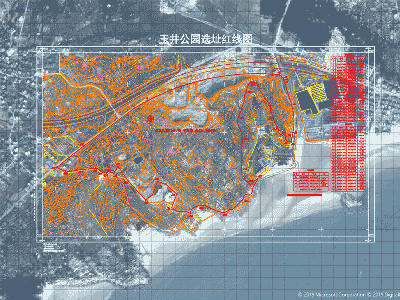
Open the drawing that includes the red line (boundary) with coordinates and the topographic map, turn on all layers, make sure all information are visible (no missing fonts) and look for the information at the left lower corner and the coordinates at the four corner.
Check your drawing:
-
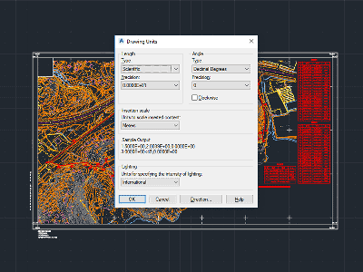
Units: China works with metric system, therefore drawing unit are [m]. Two settings need to be checked, one for the AutoCAD drawing units and one for the drawing's geographic coordinate system settings.
- for the drawing settings: use the command
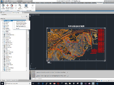
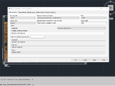
in the command line - for the geographic coordinate system settings: In Toolspace, on the Settings tab, right-click the drawing's name at the top of the collection, and click Edit Drawing Settings, go to Units and Zone tab and select under Drawing Units Meters.
Check some known distances in the drawing like a road with and scale your drawing if necessary.
- for the drawing settings: use the command
-
Direction: Ensure that your view is "TOP" and set to World coordinate system (WCS) Rotate the drawing if necessary.
-
Position: Check values of known coordinates (like the four corners, red line). Move the drawing if necessary.
Be aware the coordinate values in the four corners use period to separate thousands groups and comma as decimal separator, AutoCAD use it vice versa.
Make your coordinates visible in the status bar and/or place some coordinate annotation to known points. -
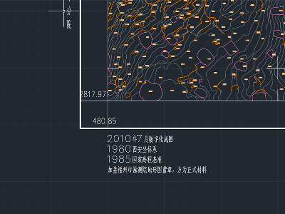
Check for additional information: Topographic drawings have in the lower left corner history information, like the drawing was translated to 1980 Xian Coordinate System.
Find the geographic coordinate system
-
Find the underlaying coordinate system based on the drawing information and known coordinates. Topograhic maps most likely in Xian80 with Gauss-Krueger Coordinates in 3 Degree Zones. In our sample also the drawing history states that the coordinate system is Xian 1980. The coordinate for the lower left corner are North 2817.9781 (Y: 2817 9781.00 m) and for East 480.85 (X: 480850.00 m).
-
Set Approximate Geographic Location and coordinate system:
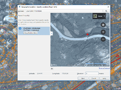
Open the drawing In AutoCAD use the dialog from the Insert tab/Set Location from Map (the display of the maps require a login to an Autodesk account) or use GEOGRAPHICLOCATION M in the command line. Zoom to the project (use first road map for fast zooming and if you are close enough change to areal view) are and set a marker in the project area (Mouse right click and drop marker).
Alternative find the coordinates from Bing or Google map (both showing Latitude/Longitude decimal degree from the WGS84 coordinate system) and use the to set the marker).
In our example for Pingtan: 25.465, 119.793.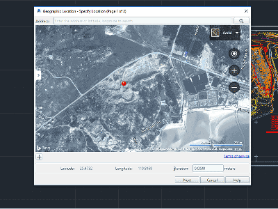
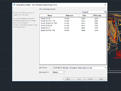
Hit next and you will see the list of coordinate systems that cover this area. Narrow down the selection based on the drawing information by using the in the search field.
In our example put in to the search field: Xian80. There will 6 coordinate systems remain. (EPSG:2334, EPSG:2346, EPSG:2345, EPSG:2346, EPSG:233, EPSG: 2364 and EPSG:2385)
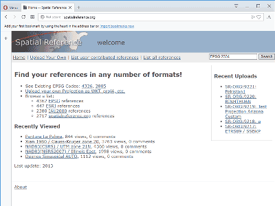
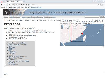
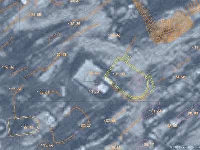
Go to http://spatialreference.org and read the information about each of the geographic coordinate system (search with EPSG:XXXX) and zoom on the map into the project area and compare the coordinates. Select the system that fit with his bounds, scope and coordinates:
In our example:
EPSG:2334, EPSG:2346 -- our project is slightly out of the boinds (red rectangle)
EPSG:2345, EPSG:2346, EPSG:2335 -- our project is in the bounds, but the scope (medium scale topographic mapping) and thecoordinates are not matching
EPSG:2364 -- the scope (Large scale topographic mapping, cadastral and engineering survey) and the Y- coordinates are matching, but the X-coordinates are about 40.000.000 m away
EPSG:2385 -- the scope (Large scale topographic mapping, cadastral and engineering survey) as swell as X and Y- coordinates are matching
The used coordinate system is EPSG:2385, Xian80.GK3d/CM-120E.

Go back to Civil 3D and select this system. Hit Next and Civil 3D is asking for a point, select one in the center of your project area (we will adjust further in the next step) and confirm the north direction with 90 Degree, the Bing road map appears as background of your drawing.
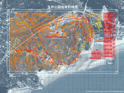
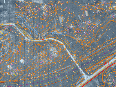
Change to Areal Map view. The map has some offset, based on the accuracy of the input
Adjustment of the background image
We are adjusting the settings by using a visible remarkable object of the drawing (road crossings, remarkable buildings) and the geographic coordinate system's marker. In the Geolocation tab use Edit Location from Map again, but this time using the Areal view, drag to marker to a well identifiable point (make sure object snap is turned off), confirm coordinate system (no change) and click on the identical point in the drawing and confirm the angle to north (no change). Repeat until satisfying accuracy.
Clip the map to your area of interest by using Geolocation Capture Area, turn the under laying online map off and set the geoimage resolution to fine.